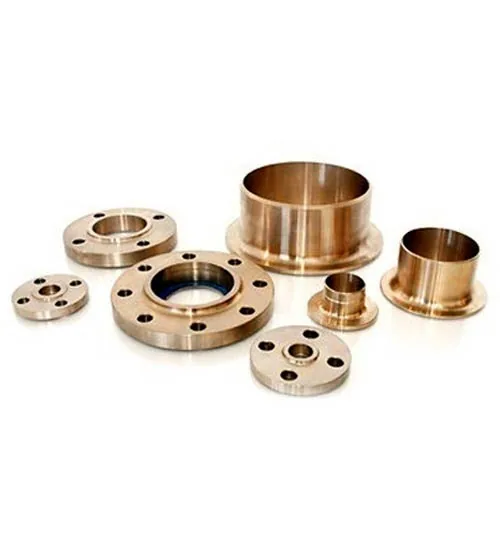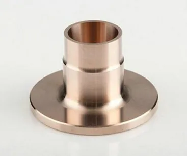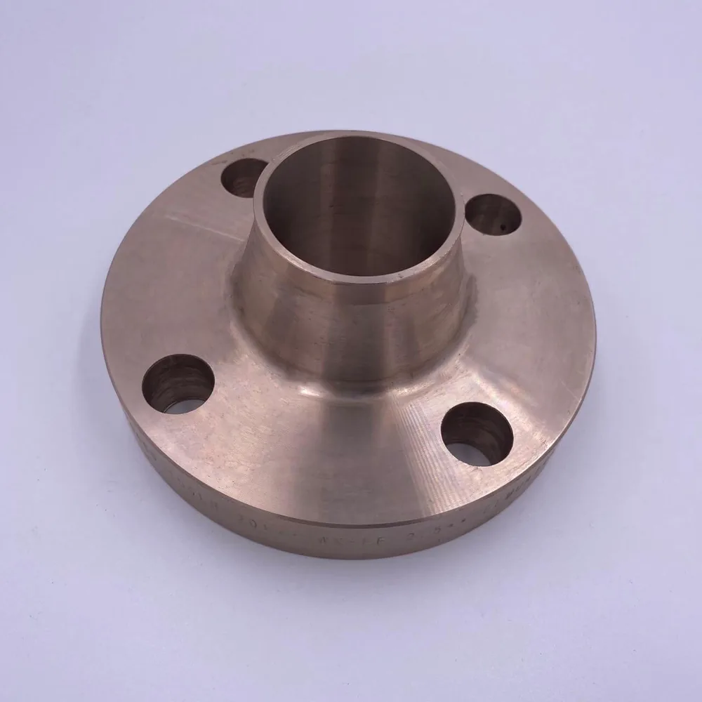
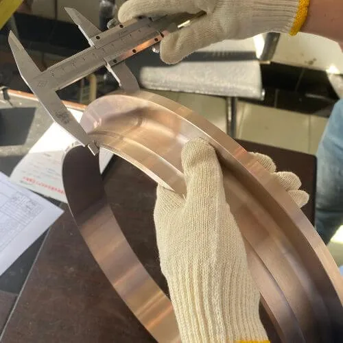
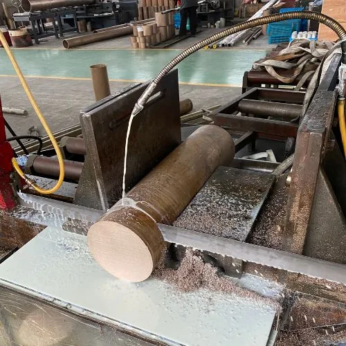
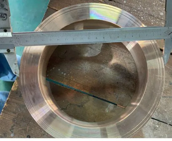
When custom flanges are needed
- Replacement of an existing flange where standard dimensions no longer apply
- Equipment connections with non-standard bolt circles or hole sizes
- Special bore, hub or thickness requirements
- Metric or legacy-standard flanges for US-installed equipment
- Customer or class-society specifications that modify a standard flange
What can be customized
Dimensions
Outside diameter, thickness, hub length, bore and overall height can be set to your drawing.
Drilling
Bolt circle diameter, hole size, hole count and tapped holes per drawing.
Facing
Raised face height, flat face, ring grooves, serrated or smooth finish, and special sealing faces.
Configuration
Blind, weld neck style, slip-on style, orifice taps, drain or vent connections and combinations of these.
Material
Cu-Ni 90/10 or 70/30, with the ASTM or ASME specification you call out.
How we work from drawings
Our team reviews your drawing for manufacturability and asks about anything unclear before quoting. Tolerances, surface finish and critical dimensions should be marked on the drawing. Where a drawing conflicts with a standard that is also called out, tell us which takes precedence.
You can send drawings in PDF, DWG, DXF or STEP format, or a dimensioned sketch if no drawing exists yet. The enquiry form accepts these file types.
Standards, materials and documentation
We keep the dimensional drawing, the material standard and the project requirements separate when quoting. Custom flanges are produced in Cu-Ni 90/10 (UNS C70600) or Cu-Ni 70/30 (UNS C71500) to the ASTM or ASME material specification stated in your purchase order.
Manufactured to applicable ASME/ASTM requirements based on project specification. MTCs, dimensional inspection reports, certificates of conformity, PMI and third-party inspection can be arranged according to project requirements.
What to include with your drawing
- Alloy and material specification
- Quantity and delivery date
- Critical dimensions and tolerances
- Facing and surface finish requirements
- Inspection and documentation requirements
- Mating equipment or flange details if fit is critical
Technical summary
Values below are references, not guarantees. Size range and pressure class depend on flange type, size, alloy and the applicable standard, and are confirmed against your specification at quotation.
| Item | Detail |
|---|---|
| Product type | Custom flange made to drawing |
| Alloy options | Copper-Nickel 90/10 (UNS C70600) and Copper-Nickel 70/30 (UNS C71500) |
| Typical material forms | ASTM B151 rod and bar, ASTM B122 plate; other forms per project specification |
| Dimensional reference | Per customer drawing; ASME B16.5 / B16.47 where referenced |
| Size range (NPS) | Per drawing |
| Pressure class | Per drawing and design basis |
| Face / end type | Per drawing |
| Typical service | Replacement, non-standard and project-specific flanges |
| Documentation | Arranged according to project requirements (see Quality and Certifications) |
Copper nickel custom manufacturing flange FAQs
Can you make flanges that do not match any standard?
Yes, to your drawing. Send it with material, quantity and delivery date, and we will review feasibility before quoting.
What file formats can I upload?
The enquiry form accepts PDF, DWG, DXF, STEP, IGES, image files and common office documents.
Can you match an existing flange?
If you can send a drawing, or dimensions of the existing flange, we can review and quote a matching replacement.
How are tolerances handled?
Tolerances are taken from your drawing. Mark critical dimensions and any inspection requirements clearly so they can be reviewed at quotation.