How a spectacle blind works
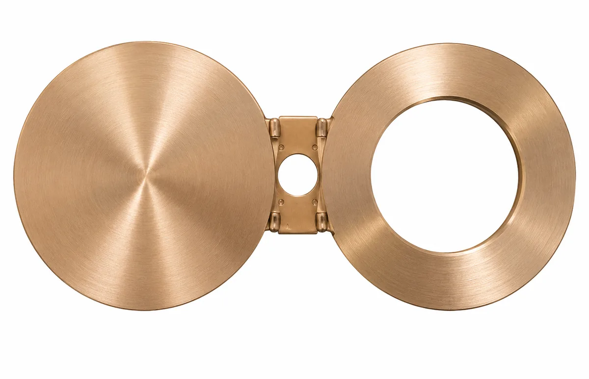
A spectacle blind, sometimes called a figure-8 blind, is a pair of discs joined by a short web. One disc is solid, the other has an opening equal to the pipe bore. It is installed between two flanges.
With the open ring in line, fluid flows. Turning the blind so the solid disc is in line closes the line positively. Maintenance crews can see at a glance which position is in use, and the solid disc gives a visible and mechanical barrier.
Where they are used
- Isolation of seawater cooling headers during maintenance
- Separating sections of firewater and ballast systems
- Heat-exchanger isolation where double block valves are not provided
- Pump isolation on seawater lift lines
- Positive isolation points in desalination intake pipework
Design and thickness
Thickness depends on size and pressure class. Your design basis, the applicable code and the dimensional standard decide it. Spectacle blinds and blanks are loaded in bending between the bolted flanges, so thickness is the key dimension.
Handle or web geometry, hanging holes and marking can be added per drawing. State whether the blind will be installed horizontally or vertically so handle position is correct.
Alloys and standards
Spectacle blinds are produced from Cu-Ni 90/10 (UNS C70600) or Cu-Ni 70/30 (UNS C71500) plate or bar. Dimensions are typically referenced to ASME B16.48 and facing and bolt pattern to the mating ASME B16.5 flanges. The ASTM or ASME material specification governs the alloy.
Manufactured to applicable ASME/ASTM requirements based on project specification.
- Sizes and classes: available as per applicable standard and customer specification
- Facing: to suit the mating flanges (RF, FF or RTJ grooves where applicable)
- Marking: size, class, alloy and heat identification per your requirement
Inspection and documentation
Dimensional checks and material identification can be arranged. MTCs, certificates of conformity and third-party inspection are available according to project requirements.
To quote we need
- NPS, class and facing of the mating flanges
- Alloy and material specification
- Quantity of spectacle blinds, paddle blanks or spacers
- Delivery date and documentation list
Technical summary
Values below are references, not guarantees. Size range and pressure class depend on flange type, size, alloy and the applicable standard, and are confirmed against your specification at quotation.
| Item | Detail |
|---|---|
| Product type | Spectacle blind / line blank |
| Alloy options | Copper-Nickel 90/10 (UNS C70600) and Copper-Nickel 70/30 (UNS C71500) |
| Typical material forms | ASTM B151 rod and bar, ASTM B122 plate; other forms per project specification |
| Dimensional reference | ASME B16.48 typical; facing to mating ASME B16.5 flanges |
| Size range (NPS) | Available as per applicable standard and customer specification |
| Pressure class | Per applicable standard and design basis |
| Face / end type | RF, FF; RTJ where applicable |
| Typical service | Positive isolation of seawater and utility lines |
| Documentation | Arranged according to project requirements (see Quality and Certifications) |
Copper nickel spectacle blind flange FAQs
What is the difference between a spectacle blind and a blind flange?
A blind flange closes a pipe end and bolts to one flange. A spectacle blind sits between two flanges and rotates to open or close the line.
Which standard covers spectacle blinds?
ASME B16.48 covers line blanks, including spectacle blinds, paddle blanks and paddle spacers.
Can the blind be supplied with a handle or hanging hole?
Yes, per drawing. State installation orientation so handle position can be set.
Do you supply the matching flanges?
Yes. We can quote the blind with matching copper-nickel flanges. Say so when you enquire.