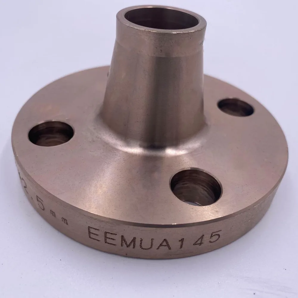
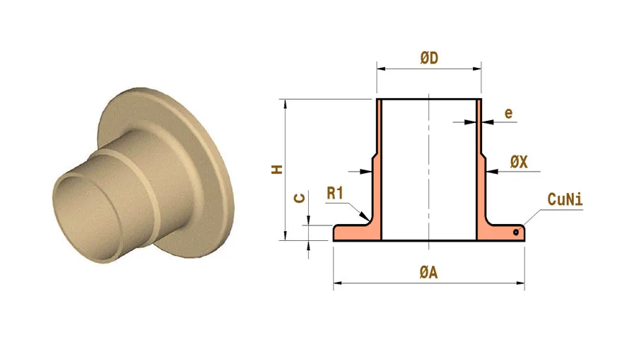
What a weld neck flange is
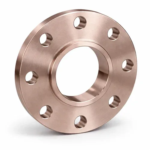
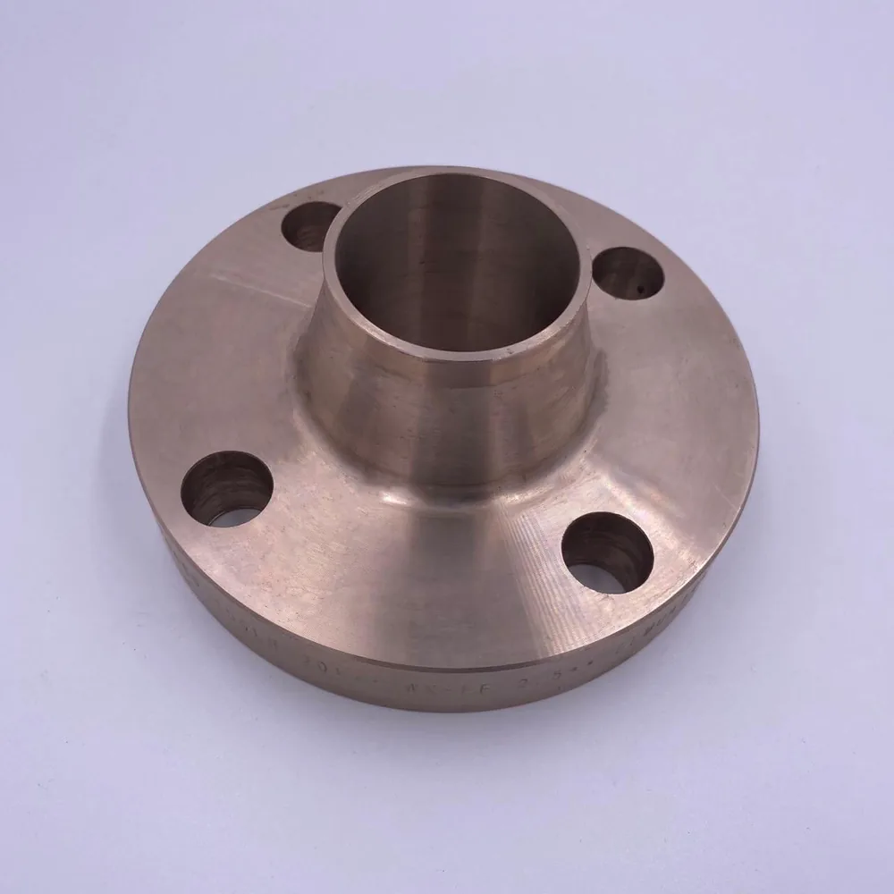
A weld neck (WN) flange has a long, tapered hub that blends from the thickness of the flange ring down to the wall thickness of the pipe. The hub end is prepared with a bevel and joined to the pipe with a full-penetration butt weld.
Because the load path runs through the hub, bending stress from the bolted joint is spread along the taper rather than concentrated at the weld. This is the main reason weld neck flanges are the default choice for critical lines.
Why weld neck construction suits copper nickel seawater lines
Copper-nickel relies on a thin, adherent surface film for corrosion resistance. Turbulence and local flow disturbance at joints can damage that film, so a flange bore that matches the pipe bore, with no step or ledge, is a practical advantage. A weld neck flange is machined to do exactly that.
Seawater lines also see vibration from pumps and thermal movement during start-up and shutdown. The tapered hub gives a gradual stiffness transition, which is why designers often prefer weld neck over slip-on on pump discharge lines, cooling-water headers and offshore firewater mains.
Alloys, material forms and standards
We machine weld neck flanges in Cu-Ni 90/10 (UNS C70600) and Cu-Ni 70/30 (UNS C71500). Four things are kept separate when we quote, because buyers often mix them up:
- Dimensional standard: flange drilling, hub and facing dimensions, typically referenced to ASME B16.5 for NPS 1/2 to 24 and ASME B16.47 for larger diameters.
- Weld end preparation: bevel geometry typically referenced to ASME B16.25 or your welding procedure.
- Material standard: the ASTM or ASME specification and product form for the alloy, for example ASTM B151 bar or ASTM B122 plate. The material specification governs chemistry and mechanical requirements.
- Project requirements: inspection scope, marking, documentation and any customer or class-society additions.
Manufactured to applicable ASME/ASTM requirements based on project specification. We do not assume that every size and class is covered by every standard; please send your specification at enquiry stage.
Sizes, pressure classes and facings
Size, class and facing availability depends on the flange type, the alloy and the governing standard. Class designations such as 150, 300, 600, 900, 1500 and 2500 describe the flange dimensional class. The allowable working pressure of a copper-nickel flange at temperature is set by the governing piping code and the project design basis, so it should not be read directly from carbon-steel tables.
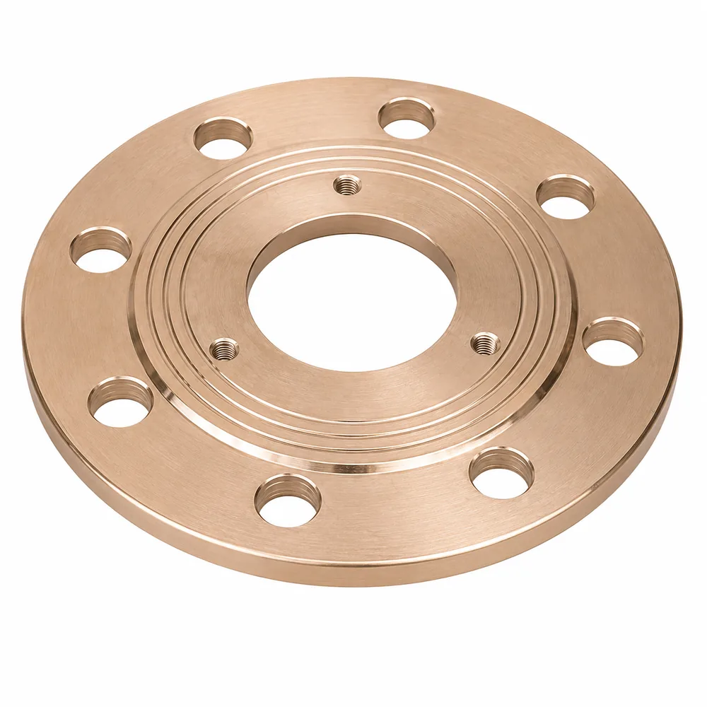
Weld neck flanges are most often supplied with a raised face (RF). Ring-type joint (RTJ) facings are available on request for higher classes, and flat face (FF) is used where the mating flange is flat faced.
- Sizes: available as per applicable standard and customer specification
- Classes: as agreed against your design basis
- Facings: RF, FF, RTJ on request
Bore, bevel and weld preparation
The bore of a weld neck flange is normally specified to match the pipe inside diameter. Send the pipe outside diameter and wall thickness (or schedule), and the bore and bevel can be produced to suit.
Copper-nickel is welded with matching copper-nickel filler metals under a qualified procedure, on clean joint surfaces. Weld procedures belong to the fabricator, but we are happy to confirm bevel details against your procedure before manufacture.
Where weld neck flanges are used
- Seawater cooling and circulation lines
- Offshore and marine firewater and ballast piping
- Pump discharge and compressor-adjacent lines subject to vibration
- Heat-exchanger nozzles on seawater-cooled equipment
- Desalination intake and brine-side piping
- Lines requiring radiographic examination of the pipe-to-flange weld
See our guide to slip-on vs weld neck flanges if you are choosing between the two.
Inspection and documentation
Visual and dimensional inspection can be carried out against your drawing or the applicable standard. Material identification, a Material Test Certificate (MTC), a dimensional inspection report, a certificate of conformity and third-party inspection can be arranged according to project requirements. They are not automatically issued on every order, so list them in your enquiry.
What to send with your enquiry
- Alloy (90/10 or 70/30) and material specification
- NPS, class and facing
- Pipe outside diameter and wall thickness or schedule
- Quantity and required delivery date
- Standards, drawings and documentation requirements
Technical summary
Values below are references, not guarantees. Size range and pressure class depend on flange type, size, alloy and the applicable standard, and are confirmed against your specification at quotation.
| Item | Detail |
|---|---|
| Product type | Weld neck flange (WN) |
| Alloy options | Copper-Nickel 90/10 (UNS C70600) and Copper-Nickel 70/30 (UNS C71500) |
| Typical material forms | ASTM B151 rod and bar, ASTM B122 plate; other forms per project specification |
| Dimensional reference | ASME B16.5 / B16.47 typical; bevel per ASME B16.25 or WPS; project drawing where supplied |
| Size range (NPS) | Available as per applicable standard and customer specification |
| Pressure class | Per applicable standard and design basis |
| Face / end type | RF, FF; RTJ on request |
| Typical service | Seawater, marine, offshore, cooling water, heat-exchanger nozzles |
| Documentation | Arranged according to project requirements (see Quality and Certifications) |
Copper nickel weld neck flange FAQs
Is a weld neck flange better than a slip-on flange for seawater piping?
Neither is better in every case. Weld neck flanges are generally chosen where vibration, pressure cycling or temperature swings are present, or where the weld will be radiographed. Slip-on flanges are used on lower-demand lines where cost and fit-up speed matter. Your design code and corrosion allowance decide.
Can the bore be matched to my pipe schedule?
Yes. Provide the pipe outside diameter and wall thickness or schedule, and our team will confirm the bore and bevel against your drawing before manufacture.
Which alloy should I specify, 90/10 or 70/30?
Both are used for weld neck flanges. 70/30 has higher strength and better tolerance of high flow velocity, while 90/10 is the more common seawater piping alloy. Our alloy comparison sets out the differences.
What documents are available?
MTC, dimensional inspection report, certificate of conformity, PMI and third-party inspection can be arranged according to your project requirements. Please state them in your enquiry.